Pillars of the Guardians: Building an interactive LED art installation
A couple of months ago I attended Burning Seed, which is an Australian Burning Man-style event. A few months prior, I’d had the opportunity to join the team producing an art installation conceived by Lucas Li, called Pillars of the Guardians. Lucas was interviewed about it on the Burning Seed website.
The art work is an interactive puzzle based on the Ten Principles of Burning Man: Radical Inclusion, Gifting, Decommodification, Radical Self-reliance, Radical Self-expression, Communal Effort, Civic Responsibility, Leaving No Trace, Participation and Immediacy.
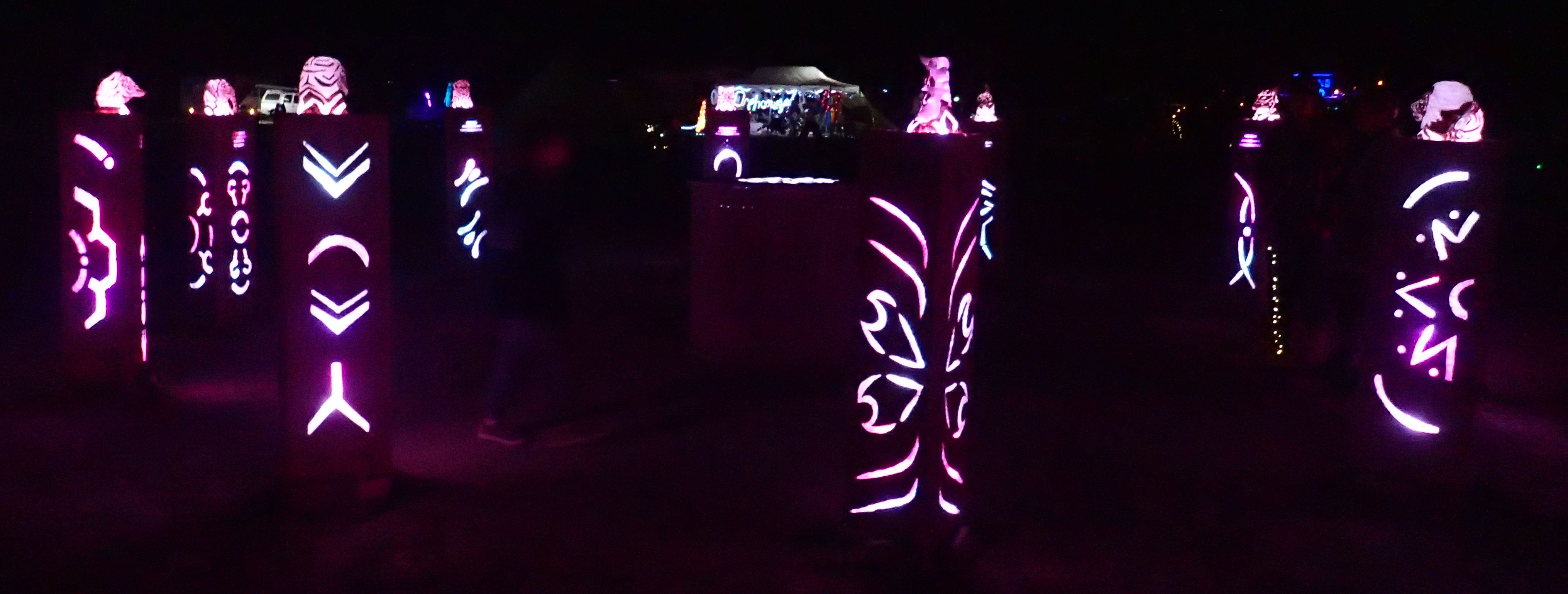
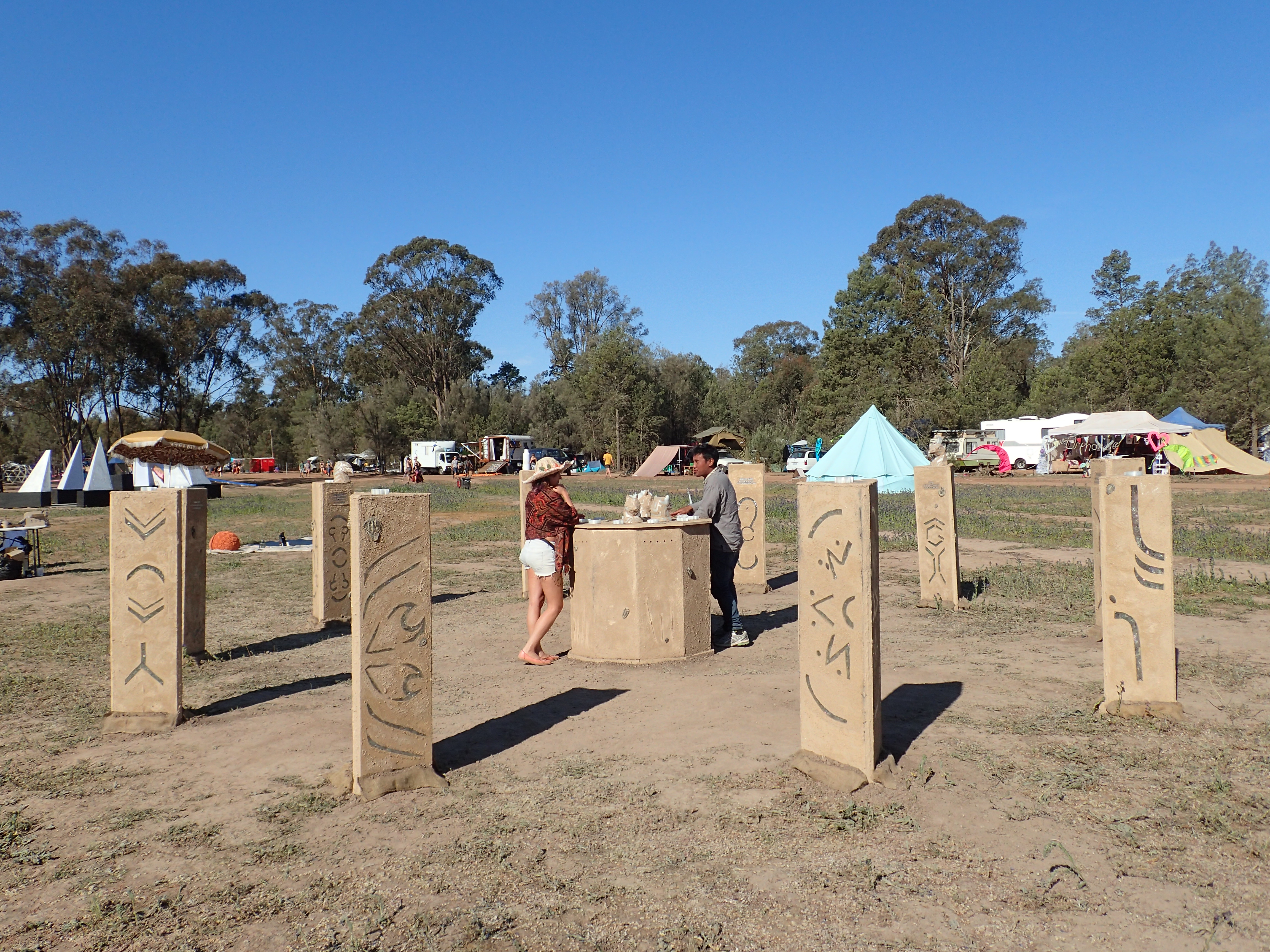
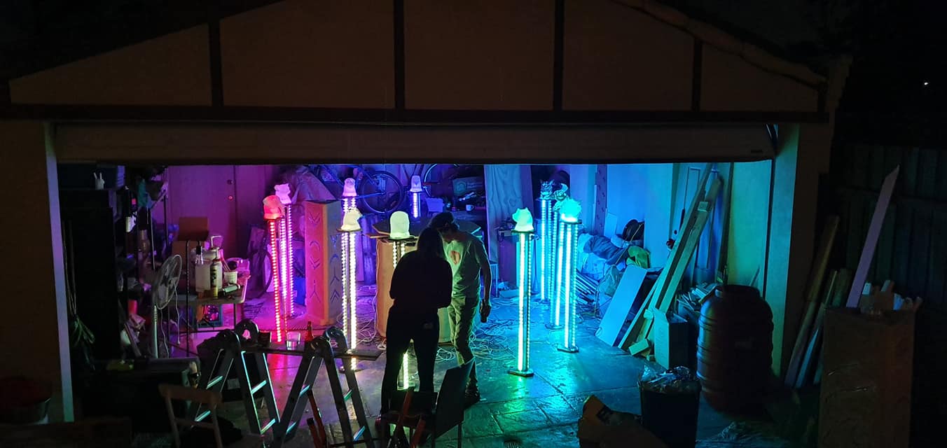
It takes the form of an “ancient monument” comprising an altar surrounded by 10 pillars. On the altar are 10 3D-printed animal heads (in keeping with the “Zoophemism” theme of this year’s Burning Seed), and each head has a different shaped slot at its base, which fits onto the top of one of the pillars. The participant is invited to correctly place all 10 heads by reading the clues on the front of each pillar, and when completed a light show is activated.
Since I’d not worked on a project of this scale or complexity before, I learned quite a bit along the way! This is a write-up about how it happened, focusing mostly on the technical side of things (since that was my main area of responsibility).
Controlling the LEDs

It was pretty much a given from the start of the project that we were going to put lots of LEDs inside the pillars and altar. I’d previously built a wearable costume using an Adafruit FLORA board (based on Arduino) and the FastLED library. But the scale of this project called for something more heavy duty.
Early on an advisor to the project pointed us to the Advatek PixLite range of controller boards, which are specifically designed for controlling large numbers of addressable LEDs. To do this, we provide data in a standard format commonly used for stage lighting called DMX512. However, DMX512 is actually a standard for data sent over physical cables, and the PixLite instead uses a wrapper format which allows DMX data to be sent via computer networks (TCP/IP) – there are two options: Art-Net or sACN.
That’s an exhausting number of acronyms! The main point is that rather than having the lighting software need to know how to control the LEDs directly, we have a layer of abstraction: the lighting software sends DMX data to the PixLite, and the PixLite knows how to talk to a wide range of common types of LED strips.
Another advantage of using the PixLite is that it has built-in power distribution and fusing. We used a PixLite 16 MkII, which can control up to 16,320 LEDs. But we were using nowhere near that many, and so long as you don’t need to draw more than 64 amps, you can power the LED strips directly through the PixLite, which makes the wiring much simpler. Each of the 16 physical outputs has a 4A fuse, so you are protected from problems due to short connections and so on. We used one output per pillar, plus another two outputs for the altar, and our power calculations indicated that we wouldn’t draw more than 3A per output even with every LED on full white.
The PixLite 16 has two power supply inputs, one for each side of the board. Each one can run at a voltage of between 5V and 30V. We used two 12V 250W power supplies, providing 20.8 amps each, which was plenty for our needs. We chose to run at 12V rather than a lower voltage in order to minimise voltage drop over the 6 metre cables we were running out to the pillars. We also made sure to use fairly large 7.5A / 18 AWG cable over these runs, which we calculated would have an acceptably low level of voltage drop.
The LED strip we bought had 30 LEDs per metre, but actually only had one chip per 3 LEDs. This meant that each 3 LEDs was the same colour, and we could only cut the strip every 3 LEDs (10 CM). This type of strip is slightly cheaper, but the main reason we bought it is that we simply could not find any 12V strip with 30 LEDs per metre which allowed each LED to be controlled individually. We could have bought 60 LEDs/metre strip, but we didn’t really need that much light, and doing so would have increased our power consumption (unless we dropped the output intensity). In the end, the strip we chose worked fine and didn’t make any noticeable difference to how the light show came out.
Sensing the head placement
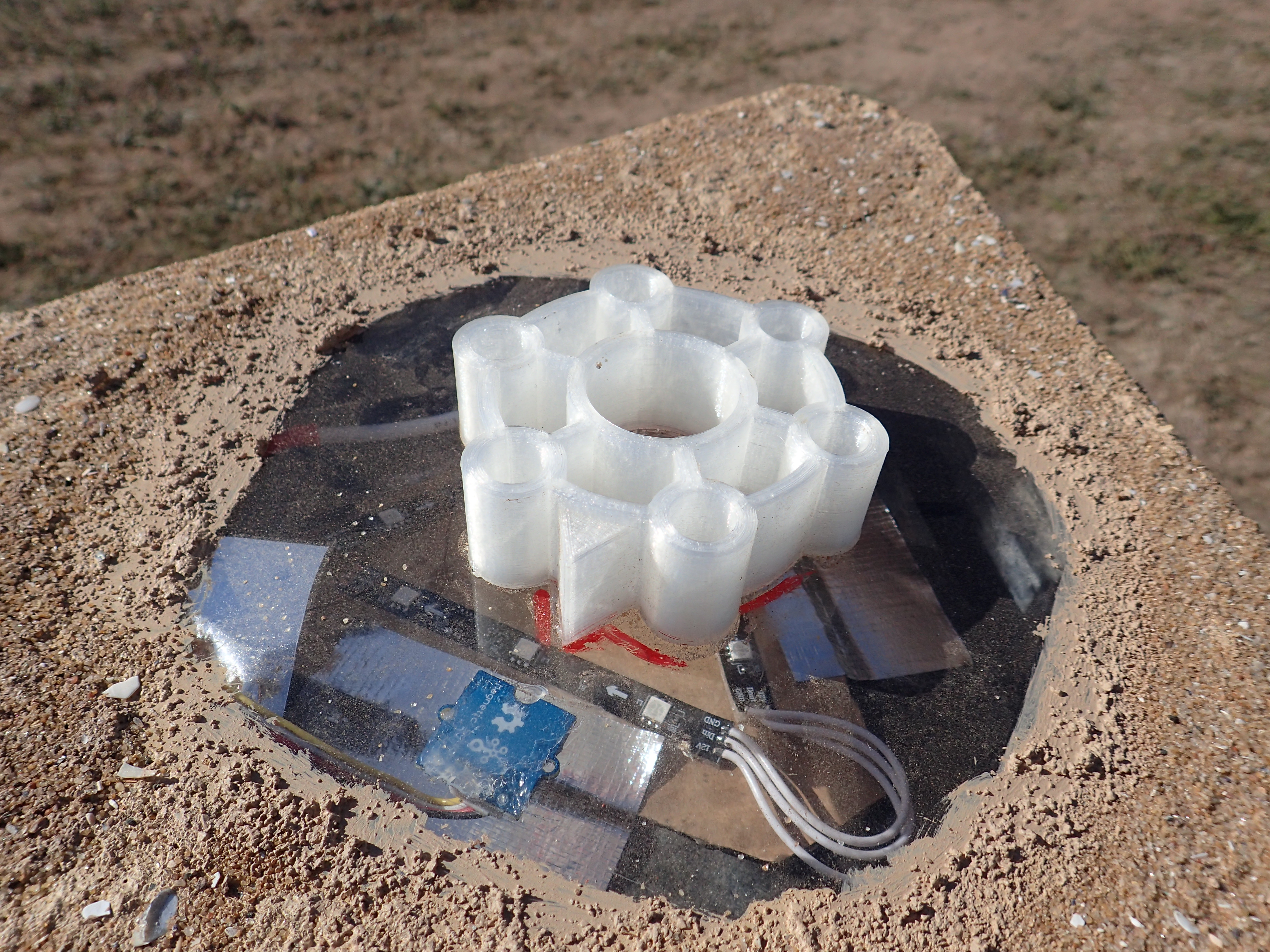
We needed to be able to detect when one of the animal heads had been placed on top of a pillar. Since the 3D-printed slots in the bottom of each head were intended to only fit onto one pillar, we used a magnetic switch in combination with two strong magnets glued inside a recess on the bottom of each head. The magnetic switch couldn’t tell us which head was present, but in theory only the correct head would be able to get close enough to the sensor to trigger it.
In reality, the patterns were such that it was sometimes possible for some of the heads to be incorrectly placed. This would then result in getting to the end and having one head left which doesn’t seem to fit anywhere. Since we had the installation staffed in order to avoid the heads disappearing, the staffer could help to resolve these problems, so it wasn’t the end of the world.
An option we discussed early on was to use RFID readers. These would have allowed us to know exactly which head was present on a given pillar, but would have been quite a bit more complicated to implement.
Originally we planned to have sensors for each head in the altar as well as in each pillar. This would have allowed us to detect when a head was in flight between the altar and the pillar, and so to turn off the LEDs which had illuminated its position on the altar. It would also have allowed us to provide some sort of pay-off to encourage participants to place the heads back on the altar after they have seen the final light show. However, as our deadline approached this part got de-scoped, and I don’t think it made a huge amount of difference in the end.
The top of each pillar was made from transparent acrylic, and the magnetic switch was glued to the underside of it using silicone sealant. There were initially concerns about the reliability of the sensors, but in actual fact they turned out to be very reliable, but also extremely position-sensitive. Most of the heads could be rotated a little bit in their slot, and during testing I found numerous instances were a few millimetres of rotation would cause the sensor not to fire. I ended up having to re-glue 7 out of 10 of them due to this problem, and used blu-tac to hold the sensor in place while the silicone cured – without this it would creep out of position.
Another problem with the sensors was interference on the wire. We initially tried using Category 5 cable for all our connections except the LED power and ground (which needed much fatter wire to prevent voltage drop). However, when we tried it we got very noisy sensor readings. I don’t know enough about electronics to be able to explain this, but we broke the sensor out to a separate 4 core alarm cable (with one core unused) and the noise went away. We then used a separate thin bell cable for the LED data connection. (In hindsight this was very fragile and we’re lucky we didn’t break any when it went in the ground. In the future I would use a thicker cable or perhaps some kind of protective conduit.)
Finally, at times I still noticed a few false positives from the magnetic switches (possibly when the cables were a bit coiled up). To alleviate this, I only considered a sensor active if we got four consecutive positive readings spaced 50ms apart. This worked great, and only added a 200ms delay, which still felt responsive enough.
Programming the light show
After assessing a few options, I decided to use LX Studio to build the light show, which was created by Mark Slee for the extremely impressive Tree of Ténéré at Burning Man 2017.
LX Studio is built on top of the ‘creative coding’ platform Processing, which is built on Java – far from my favourite programming language. Java 8 language features make it a bit more tolerable, but unfortunately Processing does not yet support them. Despite this, I’m still very happy with the decision to use LX Studio, and I don’t think I’d have been able to make something nearly as good without it. In the future, I might explore the possibility of integration with more modern JVM languages such as JRuby or Kotlin, but time constraints meant that I stuck with bog standard Java this time.
LX Studio allows you to create very sophisticated results by working at a higher level of abstraction. Rather than thinking about the colour of individual LEDs in a strip, you write code to define a 3D model for your pixels. You then write “patterns” to light up the model as desired. Patterns are assigned to “channels”, and channels can be blended together – for example you might combine one pattern to light up a specific part of the model (e.g. all the pillars) with another to apply some sort of texture (e.g. a moving sparkling effect) and another to apply some colour (e.g. fade through the colour wheel). You can even use “modulators” to affect other parameters (e.g. fade a channel in and out based on the progression of a sine wave). Finally, the output code maps the parts of your model to physical LEDs in your strip, and this is where the Art-Net data is generated and sent to the PixLite controller.
The core engine of LX Studio is a Java library called LX, which has no dependency on Processing. This means that you can run it headlessly via the command line, with no user interface. Since we planned to run our light show on a Raspberry Pi, this was useful. I figured out a way to be able to run our code via either the LX Studio UI or headlessly. This meant that I could use the UI for development, which was very helpful for figuring things out, but could then run the same code headlessly on the Pi. To achieve this, our Processing code is just a very thin wrapper which immediately calls into some shared code written in pure Java.
I’d have liked to spend more time playing with writing my own pattern code, but time got extremely tight and I ended up borrowing a bunch of patterns from the Ténéré project. I had to adapt them a bit as they were somewhat coupled to the model in that project, but it worked well enough. I hit a snag when I realised that some of them depended on helper functions from Processing, for example for Perlin noise. This was a problem because we weren’t using Processing when running headlessly. Fortunately, I realised that I could just bundle Processing into our headless .jar file, initialise a PApplet manually, and then call methods on it.
Sound
We wanted there to be a sound component to the installation. We acquired a powered PA speaker to sit inside the altar, and another team member also worked on putting small USB speakers inside each pillar, with the idea that it would be cool to have some kind of ‘surround sound’ element to the experience. Unfortunately we ran out of time for this, so we ran all the sound through the PA speaker.
LX Studio provides the ability to sample sound and change the lighting according to the music. It can either do this by playing a file directly, or by sampling the sound card input (e.g. from a microphone).
Initially I had our sound playing through LX Studio as this seemed the easiest solution. I used a “beat detector” in LX (which is actually called a BandGate in the code) to quickly fade a certain channel up and down when certain frequencies in the music exceeded a certain level. This made the head on each pillar and the centre of the altar briefly flash in time with the music.
Unfortunately, when we plugged everything in for a test 3 days before going on-site (like I said, time got tight), we noticed the sound regularly skipping. I spent the next day frantically trying to diagnose the problem and concluded that LX Studio (or more specifically, the Java sound library) was culpable. So I ended up entirely re-working how we were playing sound.
I installed PulseAudio on the Pi, and played our sound files through that, outside of LX. In order to sample the sound in LX, I configured PulseAudio to set its default ‘source’ (input) to be the monitor of the sound output. This then meant that LX could sample the default input and it would be getting the sound that is currently playing.
There was another advantage to using PulseAudio: previously we’d just been playing directly through ALSA which meant that LX would hold access to the sound card and we couldn’t play anything else. For our opening event we wanted to play another sound file outside of LX (there were dancers), which was now possible too. (PulseAudio holds access to the sound card, and acts as a software mixer.)
We were running LX as a systemd service on the Pi, so that it would start automatically on boot. In order for PulseAudio to work with this, we needed to run it in the non-standard system-wide mode because the systemd service didn’t run under a login session. I lost quite a lot of time getting this working, which hinged on putting the right things in /etc/pulse/client.conf.
After all of this, everything seemed to work really nicely during testing and for the first few days on site. Job done? Unfortunately later in the week I noticed the audio skipping again, which I was pretty gutted about having put in so much effort to avoid it!
I’m not sure what the problem was, and had run out of enthusiasm to investigate further so it’s a mystery at the moment. In testing, I’d not observed the Pi to be under high CPU load, but maybe CPU load caused the audio to fall behind. My first port of call in the future would be to look into PulseAudio’s real-time scheduling options and make sure that is set up correctly.
Finally, the Raspberry Pi’s 3.5mm audio jack is known to not produce very high quality sound. We used a USB audio card instead. You can disable the on-board audio via the Pi’s /boot/config.txt file which ensures you don’t get any issues with sound playing to the wrong output.
Putting it all together
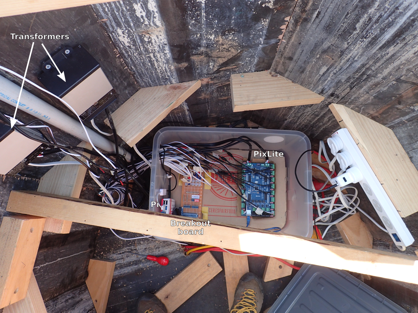
Here’s a diagram of the major pieces:

And here’s how it actually looked inside the altar:
I wrote a bit of code in Ruby to monitor the GPIO pins connected to the magnetic switches, and maintain state about where we are in the process of getting to the final light show. The state management code is not coupled to the GPIO code, allowing its logic to be tested independently of the Pi.
When a state change occurs, any registered listeners are notified. There are two listeners: a LoggingListener which simply outputs a log line for debugging, and a LightsListener which causes the lights to change in response to the event.
The lights listener calls out to a separate script which is written in Python, purely because the GPIO / state management code was originally going to be in Python too. This script translates domain-specific instructions like “activate pillar 3” to LX-specific instructions like “change the active pattern on the ‘Pillar 3’ channel to the second one”. It also plays sounds via paplay as necessary.
The communication with LX happens via the Open Sound Control protocol. Pretty much everything in LX has an OSC path which you can see by hovering the mouse over it. You can then control that element by sending an OSC message to the path – for example, sending true to /lx/channel/3/enabled will turn on the third channel.
LX allows project configurations to be saved and loaded via .lxp files, which contain JSON-serialised data. But I found it easier to programmatically configure our project via code so we didn’t use this. (Generally a change made to one pillar would need to be made 10 times, so it’s much easier to edit one line of code and loop over it.)
This took a lot of hard work, but it was pretty magical seeing people interact with the installation on site!
If you want to dig in even further, the source code is all available on GitHub.
Comments
I'd love to hear from you here instead of on corporate social media platforms! You can also contact me privately.
Add your comment